
The KeyChainino arkanoid-like game is based on a ball that bouncing on the “screen” (matrix LEDs) and a paddle used to avoid the falls of the ball in the bottom part of the screen.
The heart of the sketch is the function enabled by the overflow of the timer 1. This function is used for two things:
- Automatically update (in background) of the game values, like the ball position
- Updating the Charlieplexing Matrix according to a programmed matrix – called matrixState – that is used to turn on or off the LEDs and so to shows things on the screen.
I want to spend few words about the Charlieplexing Matrix.
The Charlieplexing Matrix – according to Wikipedia – is a technique for driving a multiplexed display in which relatively few I/O pins on a microcontroller are used to drive an array of LEDs.
Basically, with this technique we are able to drive more LEDs than the I/O pins of the microcontroller.
How? By connecting the LEDs in a particular way, you can drive the LEDs by changing the states of the microcontroller pins.

You can turn on one LED by putting HIGH one pin and LOW another pin. The others pins must be put in three-state, meaning that these pins must be put as INPUT.
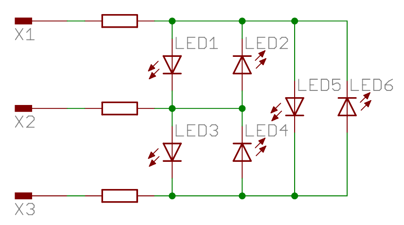
In the case showed in the image we have 3 pins X1, X2 and X3 – that could be your Arduino Pins – and 6 LEDs.
Now I will explain how to drive these 6 LEDs with only 3 pins.
Ok, we start to turn ON the LED1. What we need to do?
Simple, first we need to put the pins X1 and X2 in OUTPUT MODE, then we put the X1 pin to HIGH and the X2 pin to LOW.
What about X3? We must to put it in three-state -> INPUT. Otherwise the other LEDs connected to this pin, could be turned ON, and we don’t want this.
In code:
pinMode(X1, OUTPUT);
pinMode(X2, OUTPUT);
pinMode(X3, INPUT); //Three-State
digitalWrite(X1, HIGH);
digitalWrite(X2, LOW);
Here’s what happens. Where RED is HIGH (+V), BLUE is LOW (GND) and YELLOW is THREE-STATE (INPUT) -> HIGH IMPEDANCE:

The current flows from X1 pin to the X2 pin – from RED to BLUE – and it turns on LED1.
The LED2 will not turn ON because it is inversely polarized.
Now, If we want to turn ON LED 2? We need to reverse the output of the X1 and X2 pin. But first we need to turn OFF LED1 by putting X1 and X2 in INPUT MODE. The X3 pin is already in three-state.
pinMode(X1, INPUT);
pinMode(X2, INPUT);
pinMode(X3, INPUT);
This allows to “reset” the LEDs states by putting them OFF.
Then we can put the X1 pin to LOW and X2 to HIGH while keeping X3 to Three-State.
pinMode(X1, OUTPUT);
pinMode(X2, OUTPUT);
pinMode(X3, INPUT); //Three State
digitalWrite(X1, LOW);
digitalWrite(X2, HIGH);
Now LED2 is turned ON:

In this way the current flows from the X2 pin – through the LED2 – to the X1 pin.
Again, we turn OFF all LEDs by putting all pins to INPUT.
Next we want to turn ON LED5 in this way:
We must put X1 to OUTPUT and HIGH, X2 to INPUT and X3 to OUTPUT and LOW
pinMode(X1, OUTPUT);
pinMode(X2, INPUT); //Three State
pinMode(X3, OUTPUT);
digitalWrite(X1, HIGH);
digitalWrite(X3, LOW);
Now LED5 is turned ON

Surely you understand that these are the steps to turn ON an LED with Charlieplexing
- Put to OUTPUT the pins of the LED that we want to light up
- Put the pin connected to the anode to HIGH
- Put the pin connected to the cathode to LOW
- Put the not interested pins to INPUT – THREE-STATE
- After we turn on the LED, we wait a little time to permits to see the light
- Next we put all the pins to INPUT
Ok, so, we need to follow these steps every time we want to turn on a LED.
Remember that only ONE LED at time can be turned ON. So, if we want to turn on two or more LEDs at the same time, we need to “refresh” the LEDs very fast in order to allows our eyes to have the feeling that all the LEDs are ON at the same time.
To handle this we can create a function that do this for us. A function that will be fired from the overflow interrupt of the timer.
So we can create an array that contains all the LED pins in this way:
const byte pins[3] = {X1, X2, X3};
The pins X1, X2 and X3 must be replaced with your pins. You can use any Arduino pin like 2,3 and 4.
Next we create a multidimensional array that stores the LED connections for each pin.
  const byte LEDsPinsConnection[6][2] = {
    {0, 1}, {1, 0}, {2, 3}, {3, 2}, {1, 3}, {3, 1}
  };
Each goup of braces describes the LED connection in order – LED1, LED2, LED3, LED4, LED5, LED6.
The first value inside the inner braces is the pin position where the LED1’s Anode is connected, the second value is the Cathode’s pin position.
It means that the LED1 is connected between the pin in the position 0 and the pin in the position 1 of the pins[] array.
The LED2 is connected between the pins[1] and the pins[0]. And so on.
Remember that the first pin is always the anode.
Now we create a variable that stores all the LED states.
bool LEDstates[6] = {0, 0, 0, 0, 0, 0};
This LEDstates variable will be used to change the LEDs states. So if we want to turn ON the LED1 we can just do this:
LEDstates[0] = 1;
Notice that every array start with index 0. So, to refer to LED1 we need to work with LEDstates[0].
Well, we miss an important piece of the sketch that does the magic: Convert the previous function to a really LED turned ON.
We miss this function:
void updateLEDstates() {
  for (byte i = 0; i < 6; i++) {
    if (LEDstates[i] == 1) {
      pinMode(pins[LEDsPinsConnection[i][0]], OUTPUT); //put the LED Anode to OUTPUT
      pinMode(pins[LEDsPinsConnection[i][1]], OUTPUT); //put the LED Cathode to OUTPUT
      digitalWrite(pins[LEDsPinsConnection[i][0]], HIGH); //put the LED Anode to HIGH
      digitalWrite(pins[LEDsPinsConnection[i][1]], LOW); //put the LED Chatode to LOW
      delayMicroseconds(350);
      pinMode(pins[LEDsPinsConnection[i][0]], INPUT); //put the LED Anode to INPUT
      pinMode(pins[LEDsPinsConnection[i][1]], INPUT); //put the LED Cathode to INPUT
    }
  }
}
This function check if the first LED in LEDstates are set to 1. If it is, we set the corresponding Anode pin to OUTPUT in this way:
pinMode(pins[LEDsPinsConnection[i][0]], OUTPUT);
So we set to OUTPUT the pin in the pins[] variable at LEDsPinsConnection[i][0] position.
If i = 0, this is our pin position.

and so this pin X1
![]()
Next we set the Cathode pin to OUTPUT:
pinMode(pins[LEDsPinsConnection[i][1]], OUTPUT);
pin in the pins[] variable at LEDsPinsConnection[i][1] position. Always with i = 0.

so the pin X2
![]()
Then we put the Anode and Cathode to High and Low in order.
digitalWrite(pins[LEDsPinsConnection[i][0]], HIGH); //put the LED Anode to HIGH
digitalWrite(pins[LEDsPinsConnection[i][1]], LOW); //put the LED Chatode to LOW
We wait for 350 microseconds, and then we put the anode and cathode to INPUT.
Next we check the second LED, etc etc.
Now we need to fire this function at least 60 times per seconds. We can do that using the timer overflow interrupt:
ISR(TIMER1_OVF_vect) {        // interrupt service routine
  cli();
  TCNT1 = 65275;            // preload timer
  updateLEDstates();
  sei();
}
Learn more about the timer 1 interrupt overflow here.
Ok. Now we only need to change the LEDstates variable to change the status of any LED.
For example we can turn on and off the LEDs in order, every half second. We can do this in the loop() function:
void loop() {
  for (byte i = 0; i < 6; i++) {
    LEDstates[i] = 1;
    delay(500);
    LEDstates[i] = 0;
    delay(500);
  }
}
We can just don’t care how the LED are connected because we have simplified the complex Charlieplexing connection to a standard function!
Hurra! 😀
Here’s the complete sketch for Arduino UNO:
//the number of the pin used for the LEDs in order
const byte pins[3] = {2, 3, 4};

//the connection diagram. Each goup of braces describes the LED connection.
// The first value inside the inner braces is the LED Anode, the second value is the Cathode.
const byte LEDsPinsConnection[6][2] = {
  {0, 1}, {1, 0}, {2, 3}, {3, 2}, {1, 3}, {3, 1}
};

bool LEDstates[6] = {0, 0, 0, 0, 0, 0};

void setup() {
  // initialize timer1
  cli();           // disable all interrupts
  TCCR1A = 0;
  TCCR1B = 0;

  TCNT1 = 65275;            // preload timer 65536 - (16000000/1024/60)
  bitSet(TCCR1B, CS10);    // 1024 prescaler
  bitSet(TCCR1B, CS12);

  bitSet(TIMSK1, TOIE1);  // enable timer overflow interrupt
  sei();             // enable all interrupts
}

ISR(TIMER1_OVF_vect) {        // interrupt service routine
  cli();
  TCNT1 = 65275;            // preload timer
  updateLEDstates();
  sei();
}

void loop() {
  for (byte i = 0; i < 6; i++) {
    LEDstates[i] = 1;
    delay(500);
    LEDstates[i] = 0;
    delay(500);
  }
}


void updateLEDstates() {
  for (byte i = 0; i < 6; i++) {
    if (LEDstates[i] == 1) {
      pinMode(pins[LEDsPinsConnection[i][0]], OUTPUT); //put the LED Anode to OUTPUT
      pinMode(pins[LEDsPinsConnection[i][1]], OUTPUT); //put the LED Cathode to OUTPUT
      digitalWrite(pins[LEDsPinsConnection[i][0]], HIGH); //put the LED Anode to HIGH
      digitalWrite(pins[LEDsPinsConnection[i][1]], LOW); //put the LED Chatode to LOW
      delayMicroseconds(350);
      pinMode(pins[LEDsPinsConnection[i][0]], INPUT); //put the LED Anode to INPUT
      pinMode(pins[LEDsPinsConnection[i][1]], INPUT); //put the LED Cathode to INPUT
    }
  }
}
Every game for KeyChainino are made with this technique!
If you want to try to use Charlieplexing without connecting many wires to your Arduino boards, you can use KeyChainino!
Have a nice day!
Alessandro


This is a very clear tutorial on Charlieplex..many thanks ..thumbs up
It took me a while to get my head around this one. The key is that if you have two different paths and the forward voltage on one is higher then the current only flows in one. So in the example above when LED5 is on the 2 other LEDs in series have a higher forward voltage so don’t turn on.
Exactly!
LED1 and LED2 won’t turn on because we need to apply the double of the forward voltage.
So, In the specific case used on KeyChainino, the LEDs have 2,7v of forward voltage.
The maximum voltage that we have at the output of the microcontroller’s pins is about 3v – because the battery is a CR2032 coin cell.
So the LED5 is directly connected to the 3v and it will turn on.
LED 1 and LED 2 are connected in series and they have only half battery voltage on their poles. And they won’t turn on.
I’m trying to recreate this and I’m struggling with the getting the connections correct on the breadboard as i can only get led 0 and 1 lit. Any help appreciated.
Hi Andy, can you show me how you have connected the components on the breadboard? Thanks